This tutorial will walk you through the example project included in the app. Make sure you’ve gone through the basics before proceeding.
Open the example project by choosing Open example project from the File menu. The main window has three sections: settings to the left, the image panel in the middle and the calibration result to the right. The first thing you should see when opening the example project is this
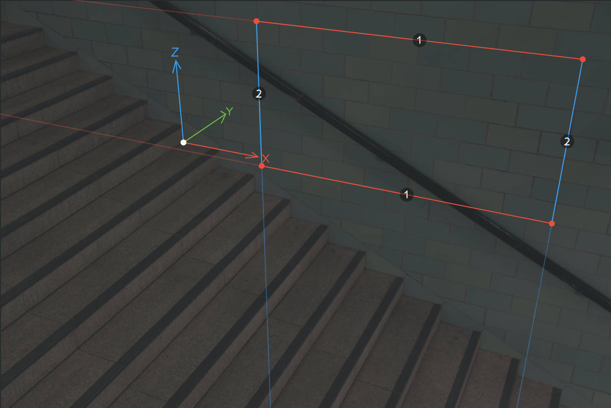
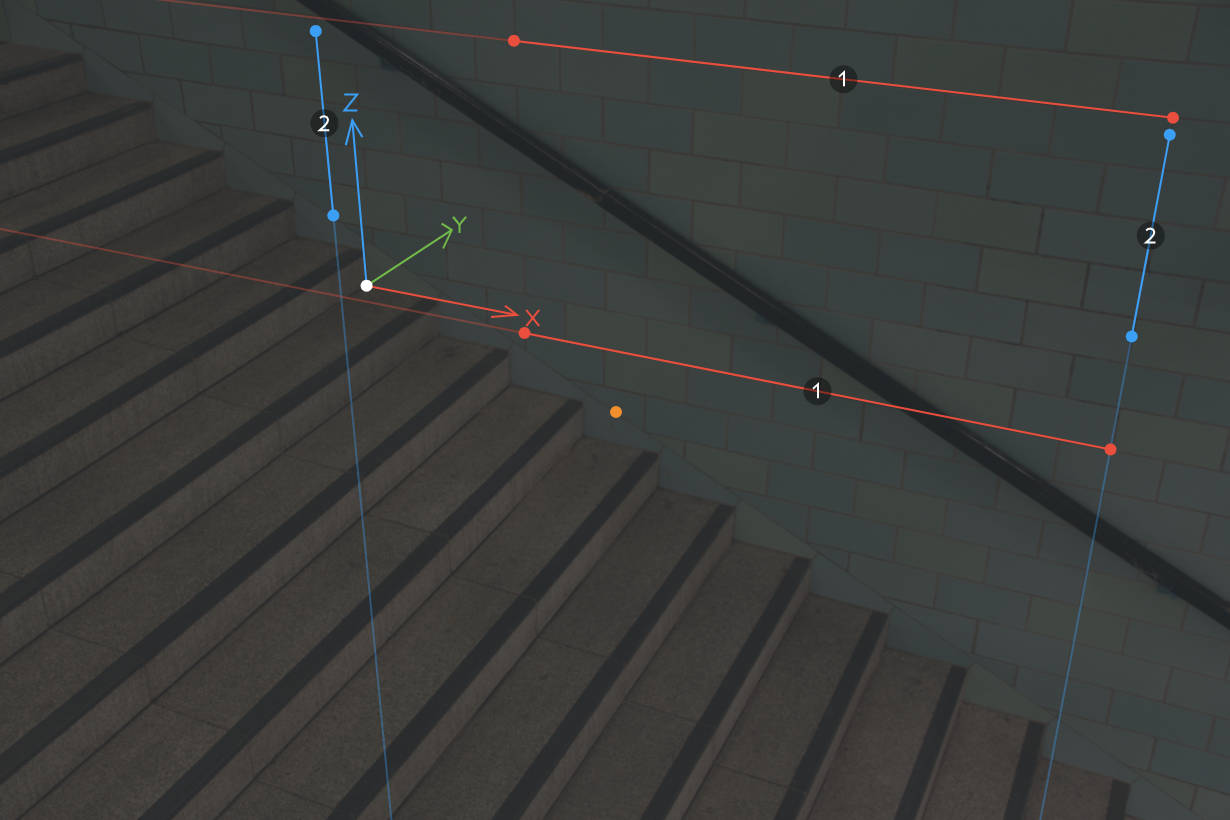
The newly loaded example project
The corners of the four sided polygon have been aligned with the corners of a real world rectangle. The edges are numbered 1 or 2, depending on which vanishing point they correspond to. The position of each vanishing point is indicated by the thinner red and blue lines. The polygon’s four control points define vanishing points for two perpendicular directions, which is enough to determine the camera’s focal length and orientation. The white control point with coordinate axes attached to it represents the 3D origin and defines the camera’s position. This is the simplest calibration setup, using only five control points.
Try dragging any of the control points and see how the camera parameters are instantly updated. For increased precision, hold down shift while dragging.
The four sided polygon control is easy to use but not always practical. To move the control points for each vanishing point independently, disable the rectangle mode option in the settings panel on the left.
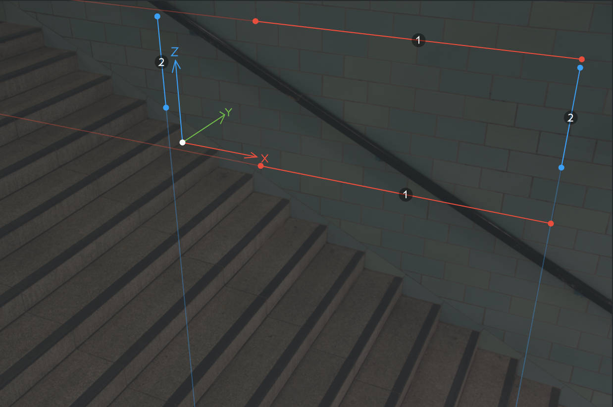
Moving vanishing point controls independently with rectangle mode turned off
To check the accuracy of the calibration, you can drag the 3D origin around to see that its axes line up with lines in the image. The 3D guide menu offers some additional types of visual assistance.
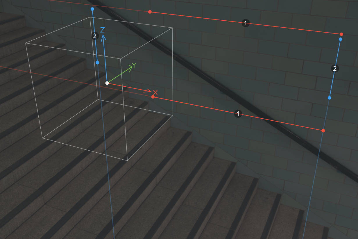
The box 3D guide
The coordinate axes x, y and z are color coded with red, green and blue respectively. The vanishing point controls each define a vanishing point in the direction of the axis given by its color. To assign an axis to a vanishing point, use the menus in the Vanishing point axes section in the settings panel on the left. Assigning vanishing point axes is useful for example when using camera parameters in external applications, that may have different conventions for which axis corresponds to the up direction.
Given two vanishing points and the position of the 3D origin, it’s possible to compute both the orientation and position of the camera. By default, the distance from the camera to the 3D origin is set to a reasonable fixed value. However, fSpy can also compute this distance based on the size of an object in the image.
Before proceeding, re-open the example project to reset any changes you may have made. The axes for vanishing points 1 and 2 should now be set to -x and -z respectively. Let’s say that the width of a wall tile is known to be 20 cm. Looking at the coordinate axes, the distance we want to measure is along the x axis, so select along the x axis from the reference distance menu. Notice that the reference distance field has been set to 0.2 m - the width of a tile - and that a new control has appeared
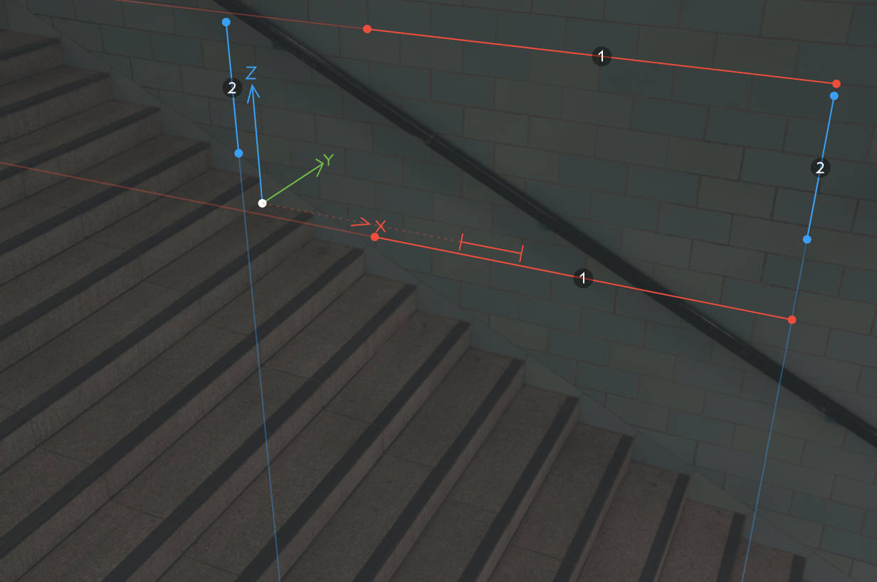
Specifying a reference distance
The dotted line from the origin in the direction of the x axis indicates that the reference distance is measured along that axis. The short red line segments are the reference distance handles and can be dragged to specify the reference distance. In the example, they have been positioned so that the reference distance equals the width of a tile.
Imagine a ray going straight through the middle of a camera’s lens. The point where this ray hits the sensor (or film) is the principal point. This point usually coincides with the midpoint of the image. In some cases, for example if an image has been asymmetrically cropped, the principal point might be somewhere else. If the position is known, select manual from the principal point menu and drag the yellow control point to the position of the principal point.
Manually specified principal point (orange control point)
If the position is not known (and you are not in single vanishing point mode), it can be computed given a vanishing point in a third perpendicular direction. Selecting from third vanishing point from the principal point menu makes a third vanishing point control appear. Once the third vanishing point has been specified, the computed principal point is shown as a yellow circle. Unless you have moved the control points too much, the computed principal point should be close to the image midpoint.
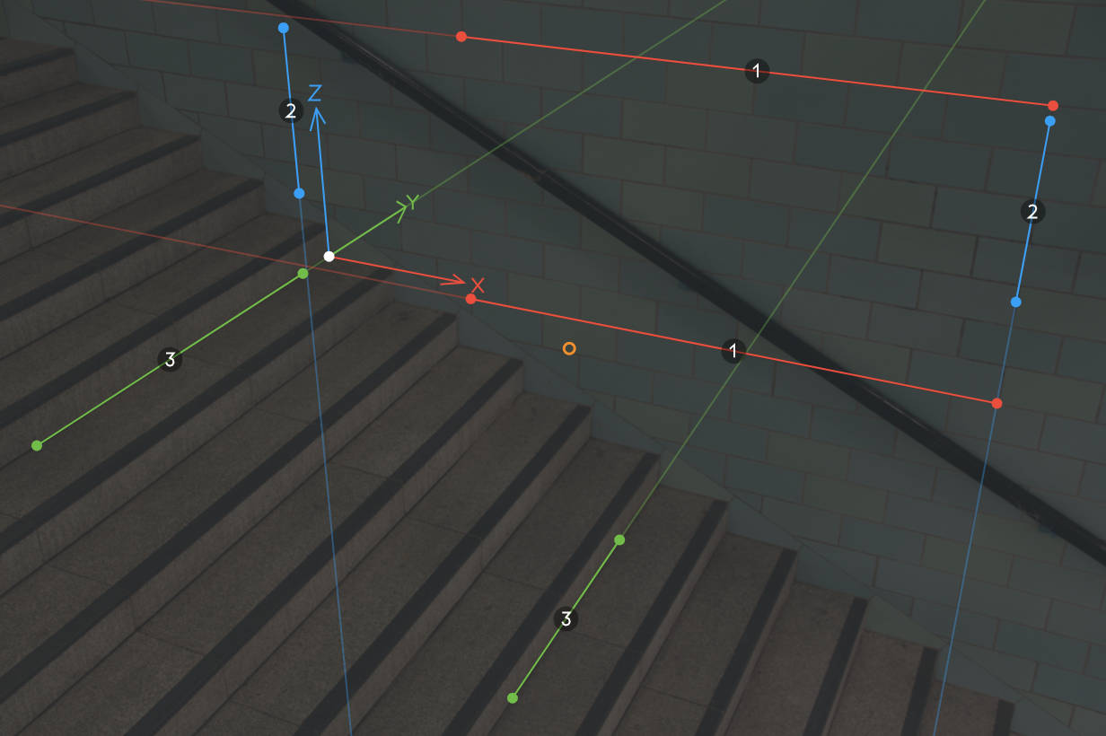
Principal point computed from a third vanishing point (orange circle)
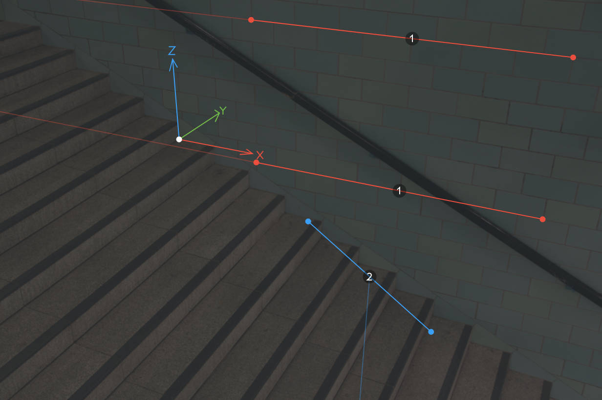
Single vanishing point calibration
So far in this tutorial, camera calibration has been performed based on vanishing points for at least two perpendicular directions. But what if only one vanishing point can be determined from an image? Then it’s still possible to compute the camera parameters given some additional information. To see how this works, select 1 from the Number of vanishing points menu at the top of the settings panel. Notice that the second vanishing point control changes and some new settings appear in the panel on the left.
When there’s only one vanishing point, fSpy relies on the user to provide
The focal length of the camera is specified in the camera data section of the settings panel. The picture in this example was taken with a Canon 60D using a 24 mm lens.
In single vanishing point mode, the control for the second vanishing point is a single line segment. This segment defines the direction between the first and second vanishing points, or equivalently, the rotation around the axis of the first vanishing point.
The panel on the right shows various computed camera parameters. If you re-open the example project, you’ll see that the focal length has been estimated to 26 mm, which is fairly close to the actual value of 24 mm. Possible sources of errors include lens distortion and that seemingly right angles may not be exactly 90 degrees.